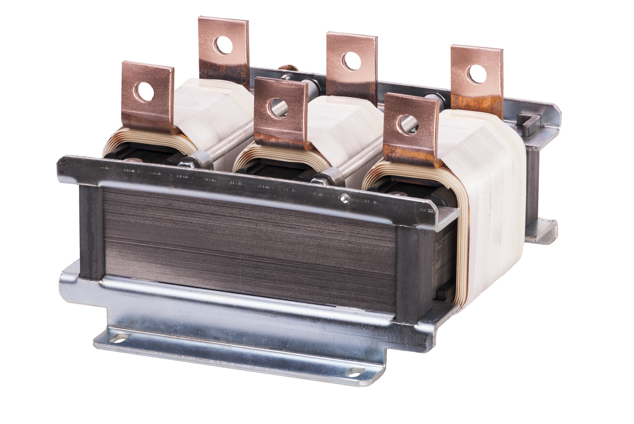
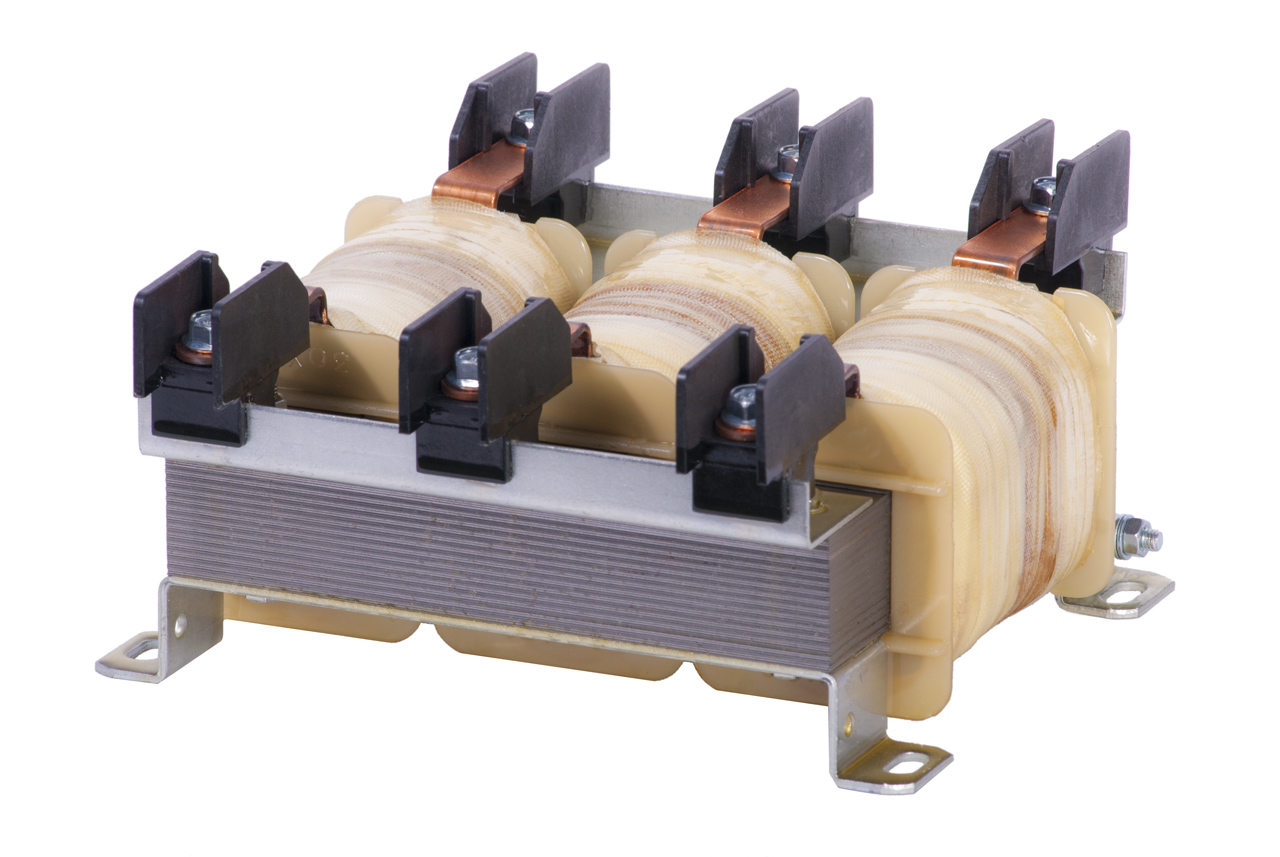
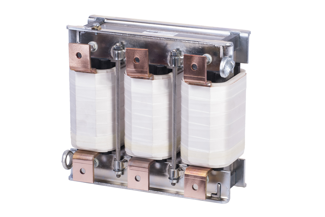
Three-phase input and output inverter reactors
The insertion of an inverter causes the presence of disturbances in the power supply network in the form of high values of current harmonics, as well as overvoltages, current ‘dips’ and ‘spikes’. If other loads such as electronic systems or other inverters are connected at the same point of the network, these are certainly influenced by the disturbances present. Therefore, a ‘decoupling’ action is necessary between these loads, which is obtained by inserting these reactors upstream of each inverter. The advantages that derive from this are the effective decoupling of the control circuits of the various loads present on the line, better protection of the diode bridges present at the input of each inverter, improvement of the harmonic content of the power supply network and reduction of electrical and thermal stresses on the capacitors of any power factor correction system present. Reactors can also be inserted in the output circuit of the inverter when standard motors are used. In this case, in fact, it is possible to maintain the voltage waveform at the inverter output within the limits that at that point is modulated by the PWM frequency.
| Technical characteristics | Value |
|---|---|
| Reference standards | IEC 61558-20 |
| Thermal insulation class | F, H (depending on construction) |
| Protection degree | IP00 |
| Frequency | 50-60Hz |
| Saturation current | 2 In (1.6 In for commutation reactors) |
| Dielectric strength test | According to standards |
| Connections | Terminal block or output bar |
| Terminals | Non-flammable Nylon or output bars |


